![]() wheelchair lifts for homes 0521.pdf
wheelchair lifts for homes 0521.pdf
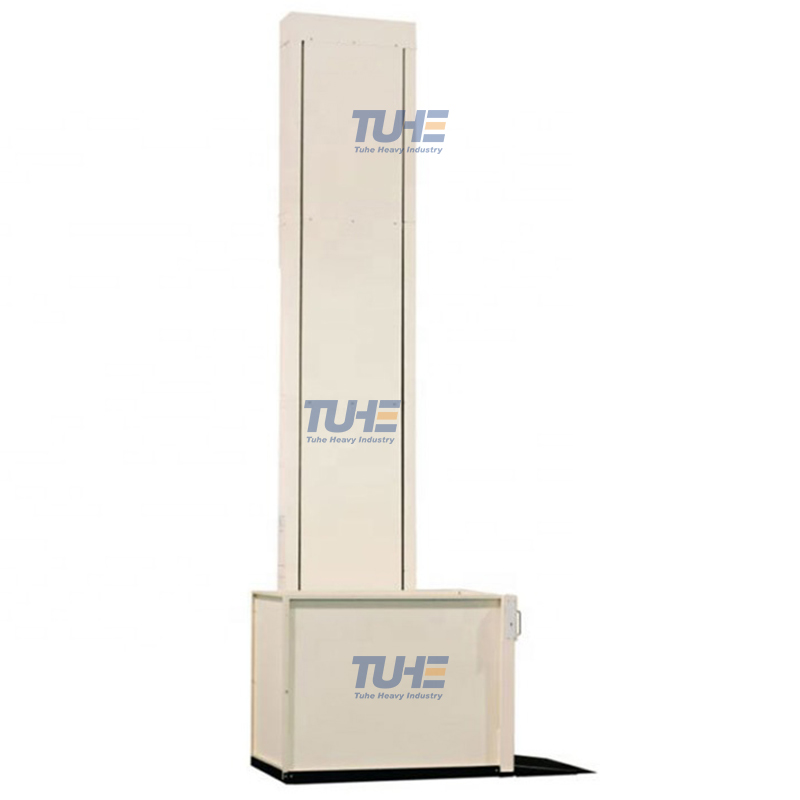
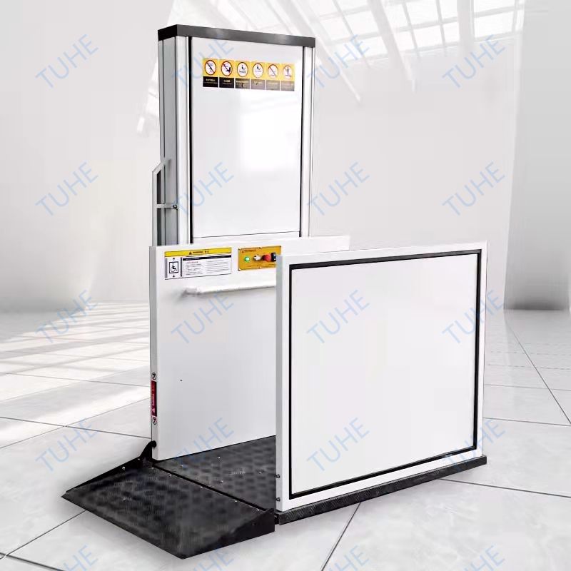
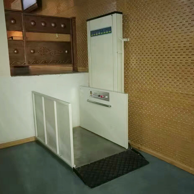
Wheelchair lift is mainly composed of a track and a lifting platform, similar to a simple small elevator. The track is embedded in the wall of the entrance and exit of the passage, and extends downward along the slope of the stairs, all the way to the interior of the tunnel. The lifting platform can be folded and placed against the wall when not in use, so that it does not occupy the space at the entrance and exit of the passage. When used by disabled people in wheelchairs, the four wheels of the wheelchair can be fixed on the platform. After pressing the switch, the lifting platform can be controlled to enter the underground passage, which is safe and convenient.
565595.webp)
2. Basic functions for wheelchair
Fully automatic operation: automatic folding and returning without manual intervention.
Manual control operating system: Manual control switch, which can manually control the action of the platform auxiliary drive system.
Operation warning, equipped with two warning modes: sound and light.
Automatic acceleration and deceleration: When the platform is about to leave/reach the landing point, it will automatically accelerate/decelerate.
Self-checking system
smart charging
Cannot run under abnormal operation
The safety pedal and safety fence cannot be operated if they are not in place
Non-contact and contact sensing obstacles will stop running in advance, and the operation will continue automatically when the obstacles are removed.
Platform abnormal operation protection device (security protection system)
Limit limit automatic stop operation protection device
Overcurrent relay protection device
Emergency stop device during operation
Can be linked with external fire alarm or alarm system
The main pedal platform has anti-skid patterns and spray paint, and the anti-skid coefficient is not less than 0.85
Easy to operate
Intelligent continuously variable speed
Wide applicability
Remote control
The detail of the wheelchair | |
Lifting Speed | 4-6m/min |
Entry & Exit | 180° |
Platform | Skid proof stainless steel with auto turning plate |
Surface | Powder coating aluminum plate |
Drive system | Hydraulic power unit system |
Power | Single phase, 220V/50HZ(Customized) |
Control | Button control and remote control |
Overload protection | Over current relay control |
Working environment | Outdoor/indoor |
Working temperature | -20°C—60°C |
Installation | No need pit, directly fixed on the concrete floor, concrete thickness not less than 200mm |
Emergency stop | Press the emergency button |
Working principle of wheelchair lifts
The owheelchair lifts is mainly controlled by PLC and frequency converter control methods. The PLC collects information and processes it and then issues instructions. The variable frequency speed regulator controls the speed of the motor according to the PLC instructions.
PLC working principle
Programmable controller, called Programmable Logic Controller in English, or PLC for short. PLC is an electronic controller based on electronic computers and suitable for industrial field work. It originates from the relay control device, but unlike the relay device, it does not achieve control through the physical process of the circuit. Instead, it mainly relies on running the program stored in the PLC memory to transform the incoming and outgoing information to achieve control.
PLC adopts the working method of "sequential scanning and continuous circulation"
1. During each scanning process, input signals are collected centrally and output signals are refreshed centrally.
2. In the input refresh process, when the input port is closed and the program is in the execution phase, there is a new state at the input end, and the new state cannot be read. The new state is only read in the next time the program scans.
3. A scan cycle is divided into input sampling, program execution, and output refresh.
4. The contents of the component image register change as the program is executed.
5. The length of the scan cycle is determined by three strips.
(1) The speed at which the CPU executes instructions
(2) The time occupied by the instruction itself
(3) The number of instructions, the current PLC scanning speed is very fast.
386059.webp)
Working principle of variable frequency speed regulator
The main circuit is the power conversion part that provides voltage and frequency modulation power to the as ynchronous motor. The main circuit of the frequency converter can be roughly divided into two categories: the voltage type is a frequency converter that converts the DC voltage source into AC, and the filter of the DC circuit is a capacitor. . The current type is an inverter that converts DC from a current source into AC, and its DC loop filter is an inductor. It consists of three parts: the "rectifier" that converts industrial frequency power into DC power, the "smoothing circuit" that absorbs the voltage pulsations generated by the converter and inverter, and the "inverter" that converts DC power into AC power. Transformer".
Rectifier
Recently, diode converters are widely used, which convert power frequency power into DC power. Two sets of transistor converters can also be used to form a reversible converter. Since its power direction is reversible, it can perform regenerative operation.
Smooth wave loop
The DC voltage rectified by the rectifier contains a pulsating voltage six times the frequency of the power supply. In addition, the pulsating current generated by the inverter also causes the DC voltage to fluctuate. In order to suppress voltage fluctuations, inductors and capacitors are used to absorb pulsating voltage (current). When the device capacity is small, if the power supply and main circuit components have margin, the inductor can be omitted and a simple smoothing circuit can be used.
inverter
Contrary to the rectifier, the inverter converts DC power into AC power at the required frequency. By turning on and off six switching devices at a determined time, a three-phase AC output can be obtained. Taking a voltage type PWM inverter as an example, the switching time and voltage waveform are shown.
Control circuit
It is a circuit that provides control signals to the main circuit that supplies power to asynchronous motors (voltage and frequency are adjustable). It has a "calculation circuit" for frequency and voltage, a "voltage and current detection circuit" for the main circuit, and a "speed detection circuit" for the motor. , consisting of a "drive circuit" that amplifies the control signal of the arithmetic circuit, and a "protection circuit" for the inverter and motor.
(1) Calculation circuit: Compares the external speed, torque and other instructions with the current and voltage signals of the detection circuit to determine the output voltage and frequency of the inverter.
(2) Voltage and current detection circuit: Isolated from the main circuit potential to detect voltage, current, etc.
(3) Drive circuit: the circuit that drives the main circuit device. It is isolated from the control circuit to turn on and off the main circuit components.
(4) Speed detection circuit: The signal of the speed detector installed on the asynchronous motor shaft is used as the speed signal and sent to the calculation loop. According to the instructions and calculations, the motor can run at the command speed.
(5) Protection circuit: detects the voltage, current, etc. of the main circuit. When overload or over voltage and other abnormalities occur, in order to prevent the inverter and asynchronous motor from being damaged, the inverter is stopped or the voltage and current values are suppressed.
907251.webp)
503.webp)
698.webp)
660.webp)